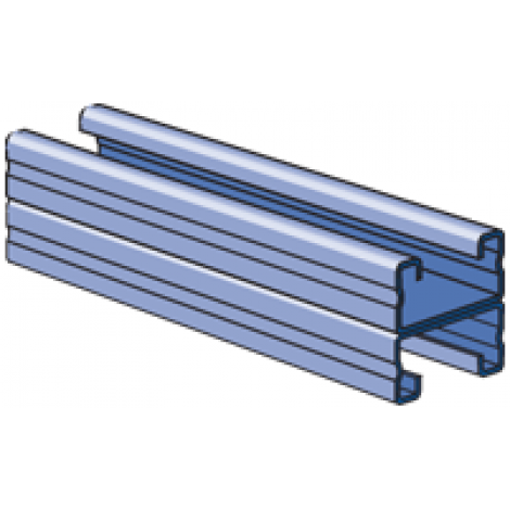
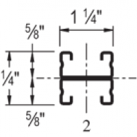
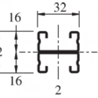
| Elements of Section - A4001 | ||
| Area of Section | 0.264 in2 (1.7 cm2) | |
Axis 1-1 | Axis 2-2 | |
| Moment of Inertia (I) | 0.037 in4 (1.5 cm4) | 0.058 in4 (2.4 cm4) |
| Section Modulus (S) | 0.058 in3 (1.0 cm3) | 0.093 in3 (1.5 cm3) |
| Radius of Gyration (r) | 0.372 in (0.9 cm ) | 0.469 in (1.2 cm ) |
| ||||||||||||||||||||||||||||||||||||||||||||||||||||||||||||||||||||||
| Beam Loading - A4001 | ||||||
| Span (in) | Max Allowable Uniform | Defl at Uniform load (in) | Uniform Loading at Deflection | Lateral Bracing Reduction Factor | ||
| Span /180 (lbs) | Span /240 | Span /360 (lbs) | ||||
| 18 | *350 | 0.02 | *350 | *350 | *350 | 1.00 |
| 24 | *350 | 0.06 | *350 | *350 | *350 | 1.00 |
| 36 | 330 | 0.19 | 330 | 270 | 180 | 0.97 |
| 48 | 240 | 0.32 | 200 | 150 | 100 | 0.89 |
| 60 | 200 | 0.52 | 130 | 100 | 60 | 0.82 |
| 72 | 160 | 0.72 | 90 | 70 | 40 | 0.74 |
| 84 | 140 | 1.00 | 70 | 50 | 30 | 0.67 |
*Load limited by weld shear | ||||||
Notes:
- Above loads include the weight of the member. This weight must be deducted to arrive at the net allowable load the beam will support.
- Long span beams should be supported so as to prevent rotation and twist.
- Allowable uniformly distributed loads are listed for various simple spans, that is, a beam on two supports. If load is concentrated at the center of the span, multiply load from the table by 0.5 and corresponding deflection by 0.8.
- The lateral bracing factor should be multiplied by the load to determine the load retained based on the distance between lateral braces.
Bearing Load on Channel:
 |  |
| Max Load 1,400 Lbs 635 Kg | Max Load 1,000 Lbs 454 Kg |