- Along this vertical line locate the (maximum usable) horizontal bracing height line.
- The arc line that intersects the point formed by the intersection of the two lines, indicates the brace required.
- 30° - 60° minimum - maximum brace angles are indicated for maximum effect.
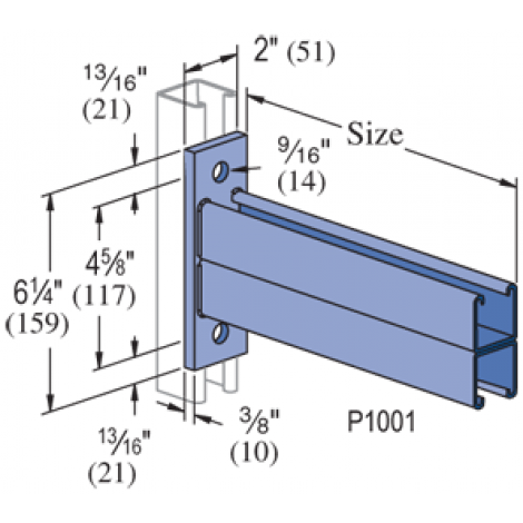
Standard Dimensions:
- Hole Diameter: 9/16" (14mm)
- Hole Spacing (From End): 13/16" (21mm)
- Hole Spacing (On Center): 1-7/8" (48mm)
- Width: 1-5/8" (41mm)
- Thickness: 1/4" (6mm)
Note:
- When used for mechanical supports, load capacities of brackets and fittings should be in compliance with the American Standard Code for Pressure Piping.
Material:
- Fittings, unless noted, are made from hot-rolled, pickled and oiled steel plates, strip or coil, and conform to ASTM specifications A575, A576, A635, or A36. The fitting steel also meets the physical requirements of ASTM A1011 SS GR 33. The pickling of the steel produces a smooth surface free from scale.
Many fittings are also available in stainless steel, aluminum and fiberglass. Consult factory for ordering information.
Application:
- All parts drawings illustrate only one application of each fitting. In most cases many other applications are possible. The channels shown in the illustrations are P1000, 1-5/8" square, except where noted otherwise.
- All 9/16" diameter holes use 1/2" x 15/16" hex head cap screws and 1/2" nuts - P1010, P4010 or P5510 - depending on the channel used. Nuts and bolts are not included with the fitting and must be ordered separately.
Dimensions:
- Imperial dimensions are illustrated in inches. Unless noted, all metric dimensions are shown in millimeters.
Design Bolt Torque:
Design Set Screw Torque:
Note: Caution should be taken not to overtighten the set screw
Design Load:
- Design load data, where shown, is based on the ultimate strength of the connection with a safety factor of 2.5, unless otherwise noted.
Beam Clamps:
- Clamps are designed to be used with W, M, S and HP Shape beams, Standard C and Miscellaneous MC Channels, Angles and Structural Tees.
- Clamps must be used in pairs where indicated.
- For beam clamps with HG finish, standard hardware is EG finish. For optional stainless steel hardware, please contact the factory for availability.